 |
 |
 |
 |
|

Vydáno dne 12. 08. 2020 (4520 přečtení) |
|||||||||||||||||||||||||||||||||||||||||||||||||||||||||||||||||||||||||||||||||||||||||||||||||||||||||||||||||||||||||||||||||||||||||||||||||||||||||||||||||||||||||||||


|
přepnout na českou verzi |

I had a graphical OLED display module of 128x64 pixels, size 1.3 inches, with control via I2C (TWI). I2C is a purely serial communication, basically just one (SDA) wire. The second wire (SCL) carries just clock frequency for synchronization. I2C is slower than communicating with the HD44780 controller , which is used in most alphanumeric LCD displays. That's why I was quite curious how it would perform.
The schematic of the frequency counter - scale is very similar to the previous one. It basically differs just by connecting the display. I have experience from previous designs (stereo radio, FM-TRX), that OLED displays interfere quite a lot via the power supply bus. Individual groups of pixels (rows) are lit sequentially (multiplex). Although the average supply current is not high, the individual current pulses are probably quite large. Therefore, I used a separate voltage regulator and filter to power just the display so that it is sufficiently separated from other circuits.
One more note:
Thanks to the multiplexed lighting of individual rows, it is also quite a problem to take a decent looking photo, or even a video of a lit display. With a short exposure time, only some pixels may be lit in the photo, while with a longer exposure, some may look burnt. In videos, there is a strong stroboscopic effect. Although these displays show very nice and contrast picture in reality, it does not look like that in photos or videos.
 |  |  |
| Schematics of scale-counter In higher resolution | PCB design - front side | PCB design - back side |
List of components (in new window)
I know from www statistics that readers don't like links to other articles (they don't click them). Therefore, I basically copied the description of the counter function from the previous article except for small changes.
Scale-counter features:
- Possibility of user setting of IF (BFO) frequency. Setting step 10Hz.
- Storage of up to 4 different IF (BFO) frequencies for different types of modulation. (BFO frequency for CW, LSB, USB may vary)
- Types of modulation switching options:
- button on the panel (information on the display and on the JP4 output connector)
- using logic levels on input connector JP4 (information on the display)
- Supply voltage measurement.
- The measured frequency and the actually set modulation are sent via a serial line to the PC log-book.
- The counter contains a pre-divider by two and four, which increased the measurement range.
Scale - frequency counter - principle of function:
As an input amplifier, I used the original, old circuit, which works fine for me. Somehow I couldn't get a high frequency J-FET transistor with N channel in SMD design. That's why I used transistors in standard TO92 packages. There is a BF245(B) at the input. In the next stage, there is an ordinary "audio transistor" (fT=300MHz) because we don't need anything better for this purpose. I used a known "trick" with a resistance trimmer R11, which sets the voltage at the input to the 74HC74 divider to a treshold level. It would probably be better to use some IC with a Schmitt circuit at the input, but I didn't find any suitable one. And I didn't want to put another case with six inverters there, just because of Schmitt's input. There are SMD circuits, for example with one inverter (for example 74HC1G14 case with 5 pins), but these are not quite commonly available (usually only to order in larger quantities).Using a jumper, we can select the input to the MCU counter either directly, divided by two, or divided by four. But then we have to use the correct firmware version. What I like the most is the version with a divider of two. It works up to about 18MHz and one reading cycle takes 200ms. Therefore it takes place approximately 5 times per second. The trimmer R11 must be set slightly differently for direct input to the MCU or to 74HC74 (74HCT74). During testing, I found that the direct input 1:1 (if we do not use a divider) has a slightly lower sensitivity.
There are 3 firmware versions stored in the DOWNLOAD section. Each is intended for a different input frequency division setting (1:1, 1:2, 1:4).
I made the processing in the MCU almost the same as in the previous version. I used a 16-bit counter that increments a byte-type auxiliary variable each time the OVF (overflow) occures. This forms a 24-bit counter, ie up to 224 = 16 777 216. It counts input periods for 100ms, 200ms or 400ms, depending on whether and what frequency division at the input we have chosen. After this time the frequency is calculated from the current state of the 16-bit counter and the auxiliary variable. It is combined with the set value of the IF (BFO) frequency and then sent to the display. The IF (BFO) frequencyis added or subtracted, according to the frequency plan of the radio. It follows from the above that the counter counts tens of Hz (10Hz). This seems to me like a good compromise between speed and accuracy. It would take too long for 1Hz to count, and we would have to wait for the value to appear during continuous tuning. In contrast, hundreds of Hz (100Hz) is already too rough for CW or SSB radio.
I made a string of the frequency with two decimal points for better orientation. One dot is between MHz and hundreds of kHz and the other one is between kHz and hundreds of Hz. Thus, with nine characters per line (including both dots), the frequency can be displayed as 99.999.99 (kHz) (but of course, it does not measure that high).
The MCU Atmega328PB runs at 20MHz from an external crystal. The crystal has no any C-trimmer for fine-tuning of the exact frequency. On the one hand, they are hard to find today, it would be too expensive and maybe too big. We will adjust the measurement inaccuracy when setting the IF frequency. We simply tune the center of the IF filter to a signal of a known frequency (for example from another radio) and in the intermediate frequency setting mode we set such a number that the scale shows exactly the frequency of this received signal after adding or subtracting of that number. I know, it is not completely correct, but quite acceptable when tuning a single-band HF radio in a range of a maximum of hundreds of kHz.
I once wrote more about it in this article (note in italics).
One AD converter input is used to measure the supply voltage. The voltage is measured in 0.02 Volt steps, but is only displayed in 0.1V step, so that the display does not flicker too much. If we hold down the right button when switching on the power supply, and then lower the supply voltage below 10V, the hundredths of Volt will also be displayed and we can set it exactly with the R8 trimmer.
Scale - frequency counter - CAT communication with computer:
Because the connection of TRX with a computer log-book is completely common nowadays (rather necessary), I also connected a UART from the MCU to the connector. It's at the TTL level, so we can directly connect any TTL UART to USB converter. For the first trials, I used a module with soldered CP210x circuit (see the picture a lot below). Communication works without any problem, but the galvanic connection to the PC via USB causes interference of a reception. It depends a lot on which computer we use. It's barely noticeable with my laptop, it's useless with my big PC. Therefore, I later used a circuit with galvanic isolation on a separate board, which I describe in this article.
 |  |  |
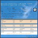
| CAT communication settings of TR4W | TR4W communicates with TRX SW20 + | It is good to reduce the poll rate. (not necessary) |
For the communication I used a very simplified protocol for Kenwood or Elecraft:
Since in this protocol all queries end with a semicolon ";", the MCU only monitors its arrival and when it arrives, it answers by sending the measured frequency and the actually set modulation. All other information is useless. I have reliably tested it with the TR4W contest log-book and an old version of ACLog by N3FJP which I have been using since about 2006. The oldest versions of ACLog 2.8 and 2.9 have a bit of communication problems. The slightly newer ACLog 3.2 works very well. I don't have any newer ones.
I set the UART speed and other parameters:
38400 bps 8 data bits 2 stop bits no parity.
In addition to the Rx, Tx and GND signals, the 5V power supply for the galvanic isolator is also connected to the connector. The other side of it is powered from the USB port.
Limitations
While testing this communication, I encountered a limitations. As I wrote at the beginning of the article, communication with the display via I2C is a bit slower. Therefore, if I have the supply voltage measurement switched ON, there is sometimes a delay in sending data to the computer via the serial line. (The MCU must measure the frequency, send it to the display, measure the voltage, send it to the display and then answer the frequency query). It also depends a lot on the PC log-book that we use. For example, the ACLog_3.2 log-book is not a problem because if it does not get an answer to the frequency query, it simply continues to use the value from the previous query. In contrast, for example, TR4W will not display anything if it does not receive a response. Thus, it may happen that if we save a QSO exactly at the moment when it does not display the frequency, this QSO will be stored without a frequency. The solution is quite simple. Just do not have the supply voltage measurement shown on the display when using the TR4W diary.
The JP4 connector can work in 3 different modes:
1: IF frequency setting:
If we hold down the left button while turning on the power, we will enter the IF frequency setting mode. The IF (BFO frequency) will be set for the type of modulation that was set before switching off. By connecting the respective pairs of pins on JP4, we can set it in steps +/- 1kHz or +/- 10Hz. Use the right-hand button to save the value (we can save it at any time) and the left-hand button to jump to the normal operation. If we set a negative value of IF, there is no space for the "-" (minus) character. Therefore, for negative IF values, the number is displayed inversely (in negative).
2: Input for setting the modulation type:
The pair of pins marked "M" (Mode-out) on the next, 6-pin connector JP3 must be open. In normal operation (frequency measurement), if we interconnect the respective pair of pins on the JP4, we will switch to the corresponding type of modulation. (from top - CW, LSB, USB, DIG). This is shown on the display and the corresponding IF (BFO) frequency is used to calculate the frequency. If we leave all JP4 pins open, we can switch the modulation type by holding down the right button (about 1 sec).
3: Output for setting the modulation type:
If we interconnect the "M" input (Mode-out) of the 6-pin JP3 connector and restart the scale-counter (turn off/on the power supply), the JP4 connector will perform as an output, and 5V voltage appears on a corresponding pin when switching the modulation. (from top - CW, LSB, USB, DIG). This allows us to switch some other circuits in our radio. To prevent damage of the MCU in the event of an output being accidentally short-circuited, I added resistors R12-R15 to the outputs.
JP3 connector
The other two outputs (inputs) AUX and S-meter on the connector JP3 are unused. There was free space, so I put them as reserve in case I need them for something in the future. For example, I was considering applying voltage from the AGC and displaying something like an S-meter. But for practical use, it seems like unnecessary nonsense, so I gave it up.
Frequency scale - setting of IF frequencies (BFO) using a serial line:
 |  |  |  |
| USB-UART converter CP210x | Communication using Hyperterminal | Termite3.4 setting com parameters | Communication using Termite 3.4 |
When I already had a connector on the board for connecting the PC log-book, it occurred to me that it could also be used to set IF frequencies. If we are in the IF setting mode (hold down the left button when turning power on), we can connect some common terminal program that can do serial communication. I tried, for example, Hyperterminal, Termite_3.4, or PuTTy.
The setting is the same as for communication with the log:38400 bps 8 data bits 2 stop bits no parity.
After connecting and entering an empty line, a text will come to the terminal with a description of what to do. Both methods of IF settings work at the same time, so they can be combined. For example, we enter the frequency from the terminal (it is faster) and save it with the right button. The IF frequency (BFO) is entered in Hz. The reason is to make it simple, even if the last digit (Hz units) is ignored when storing and then calculating the frequency.
I used a small USB-UART (TTL) converter module for serial communication. It is a CP210x chip soldered, including connectors and a few other components on a 15x20mm PCB. I bought it on ebay.com. If we only want to use it for IF settings, there is no problem. But if we want to have it permanently connected to the PC log-book, the direct connection via USB causes interference to the reception and it is necessary to use galvanic isolation, see this article.
 |  |  |
| Module for galvanic separation of the serial line | Picture of assembled PCB side A | Picture of assembled PCB side B |
Notes about mechanical design, used components:
 |  |  |
| Assembled front side | Assembled back side | Assembled, top view |
- I think it's best seen from the photos. All scale components, including the display and buttons, are on one double-sided printed circuit board.
- Most SMD components are from the front. We need to solder them before soldering the display.
- The outline of the 0.96 inch OLED display module is drawn on the printed circuit board. However, I used a slightly larger display, 1.3 inches. (That's why I had to move the buttons more sideways to fit the display.)
- The display must have the order of the terminals (from left to right) GND, VCC, SCL, SDA.
- Some displays have a problem resetting when the supply voltage rises slowly. Unfortunately, when buying displays on ebay.com, for example (but also in other global e-shops), sellers often provide bad information, such as about built-in drivers and the like. The photo below shows a sample of suitable and unsuitable displays, purchased on ebay.com, which I tried.
 |  |  |
| Example of use TRX SW20+ | Suitable and unsuitable display modules | Soldered from inside to the front panel |
- The used MCU is an Atmega328PB in a TQFP32 package (it is NOT possible to use an Atmega328P without the B at the end).
I described my method of how to solder these SMD components in this article (incuding a video).- 74HC74D or 74HCT74D in SO14 housing can be used as a divider.
- A 20MHz crystal is common, in the HC49 package low or high .
- All smd resistors and capacitors are size 1206.
- Resistor trimmers are PIHER CA6H upright.
- At the bottom of the PCB are two buttons (miniature momentary switches), to which I glued round fingerboards bought on ebay.com (I did not find any similar ones in local shops). Compared to the version with an alphanumeric display, I had to place the buttons more to the sides, because there will obstruct the bottom of the display.
Upload FW into MCU memory:
There are 3 firmware versions stored in the DOWNLOAD section. Each is intended for a different input frequency division setting (1:1, 1:2, 1:4)The program can be loaded into the flash memory via the ISP connector, for example using USB-ASP, as described in this article. When programming, we must not forget to set the configuration bits (fuses). Thus, turn off the frequency division of the oscillator by eight, change the clock frequency source to an external crystal and turn on Brown-out to 2.7 Volts (a processor reset will occur if the voltage drops below this value).
 | ||
| Setting configuration bits in Bascom-AVR | ||
Configuration bit settings in summary (for AVR-DUDE, for example):):
- Lockbits:FF
- Fusebits: FF
- Fusebits High: D9
- Fusebits Extended: FD
It is necessary to choose the correct firmware version, depending on how we connected the input frequency division (1:1, 1:2, 1:4).
I expect to publish the source code here in few weeks. But first I have to edit comments to a readable form so that they can be understood also by someone other than just me (Even I have sometimes problems. ;-))
Control and setting, using buttons:
- After loading the FW into the MCU, it works as an ordinary frequency counter.
- Left button:
- Short press - changes high x low contrast (brightness)
- Hold for 1 sec - turns off the display.(Any button turns it back On.)
- Hold when power is turned on - jumps to IF frequency setting mode (BFO). (Press again to return to frequency measurement.)
- Right button:
- Short press - display of supply voltage (push again to cancel).
- Hold for 1 sec - toggles the modulation type (if set - see connectors JP3 and JP4).
- Hold when power on - voltage measurement setting (by R trimmer). (Below 10V, it will also show hundredths of volts.)
- During IF frequency setting (BFO) - saves value to Eeprom.
Example of scale-freq.counter build in CW QRP transceiver SW20+.
Jarda, ok1hdu
Retro QRP CW transceiver na pásmo 60m (08.01.2022)
Repase retro QRP CW transceiveru SW-80+ (09.12.2020)
Inovace QRP CW transceiveru SW40+ (30.10.2020)
Stupnice - čítač s OLED grafickým displejem (18.07.2020)
Galvanické oddělení sériové linky (17.06.2020)
Nová verze stupnice-čítače k jednopásmovému KV QRP transceiveru (07.06.2020)
| Novinky |
|
07.07.2023: Update na webu DXFC Dneska jsem updatoval info na webu DXFC.
05.07.2019: Update fotoalba Do fotoalba jsem přidal pár fotografií ze:
Slovinska (červen 2019) Fotoalbum prozatím zrušeno. 05.12.2018: Update fotoalba Do fotoalba jsem přidal pár fotografií ze:
Slovinska (jaro 2018) a ze: Suchého Vrchu (zima 2005/2006). Fotogalerie je prozatím zrušena. |
| kalendář |
| |||||||||||||||||||||||||||||||||||||||||||||||||
| Radary ČHMU |
|
| Zaparkováno na: |

|
| TSL certifikát: |

|


Tento web site byl vytvořen prostřednictvím phpRS - redakčního systému napsaného v PHP jazyce.
Na této stránce použité názvy programových produktů, firem apod. mohou být ochrannými známkami
nebo registrovanými ochrannými známkami příslušných vlastníků.