 |
 |
 |
 |
|

Vydáno dne 08. 01. 2020 (11898 přečtení) |
|||||||||||||||||||||||||||||||||||||||||||||||||||||||||||||||||||||||||||||||||||||||||||||||||||||||||||||||||||||||||||||||||||||||||||||||||||||||||||||||||||||||||||||||||||||||||||||||||||||||||||||||||||||||||||||||||||||||||


|
přepnout na verzi v češtině |

Due to the overfilled 2m band, but maybe to maintain the level of sales of FM radios, the 2m band had to switch to the half channel step of 12.5 kHz and the inputs of the repeaters started using sub-tones (CTCSS, PL). Also the repeaters on the 70cm band were built quite intensively. But then came the cheap GSM mobile phones and lower tariffs for calling and FM channels of the 2m band were empty in a very short time. Today, we can hear the "weather report clubs" in the morning and a few local circles in the evening. (Experts say that the CB band has suffered a similar evolution, but I have no personal experience with it.)
Sometimes I have such feeling that some HAMs still do not understand that already for 20 years we are using the frequency step of 12.5 kHz on the 2 meters band and that the half of the channel step requires a narrower IF filter and mainly to reduce FM modulation. Just one advice for those taking part in various FM contests: Yelling into the microphone or increasing the modulation will not help. This is not SSB. If the opposite station has the narrow filter On, then your wide signal closes its squelch and your voice is stuttering from the speaker, so surprisingly, reducing modulation will increase legibility.
Despite the declining interest of FM communication on amateur bands, I was quite surprised by the interest in building simple QRP FM transceivers with DSP modules Dorji DRA818V (DRA818U), which I published in September of 2016 (English version in 2018). So I decided to develop a newer version last year. The whole QRP FM TRX is again divided into two PCBs. The boards are interconnected by two five-pin connectors, so we got rid of quite annoying work with wiring.
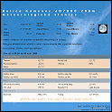
Briefly the DRA818V parameters.
The UHF version DRA818U has only a different RF range.
 | ") |  |
| DRA818V dimensions | Pins description | |
 |  | |
| limit values | some of the parameters | RF parameters |
Changes from the previous version:
I used an OLED display, mechanical rotary encoder and four buttons on the board with control electronics (front subpanel). As a control computer I used the Atmega328PB. The Atmega328P in a smd package (TQFP32) can be also used. There is no need to worry about soldering the TQFP32 housing, as I have described in this article . Due to the small size of the display and the processor, I could make this PCB a bit smaller. I also dropped the preamplifier for the microphone and placed it directly to the microphone box. This article describes the microphone. I also omitted the 1750Hz tone generation (I don't know any repeater which requires it).
Basically just for vanity I added two LEDs. Red indicates transmission (PTT), yellow indicates open squelch (Busy).I also modified the second PCB which contains the DSP transceiver, and audio amplifier. I enlarged it a bit so the voltage regulator with the heatsink can be screwed directly to the PCB. To get rid of the need to use a logarithmic potentiometer to adjust the volume, I used a voltage-controlled AF amplifier. The control voltage is generated by a PWM in MCU. In the RF low-pass filter (LPF) I used only fixed capacitors in smd design and wound coils. I modified the PCB in this area so that the filter could be easily adjusted (In the previous version I had a bit of a problem with parasitic PCB capacity, mainly in the 430 MHz band).
When I was fiddling with creating the firmware, at first I added the option of scanning any selected part of the band, then I added 20 memories for storing favorite frequencies (TX, RX and CTCSS subtones) and naming them and finally also scanning those memories. I made the firmware universal for both bands (2m, 70cm). We choose which band it will be for, when turning ON the TRX for the first time, after loading FW into a MCU (and later it can be changed too).
RF/AF board:
It is universal for both the VHF 2m or the UHF 70cm, depending on whether we plant it with the DRA818V or the DRA818U module and depending on what LPF filter components we use.
 |  |  |
| Schematics in higher resolution | Check of the Gerber files one side | Check of the Gerber files the other side |
The RF/AF board contains:
- supply voltage regulator (stabilizer)
- Dorji DSP module DRA818V (DRA818U)
- harmonics filter (LPF) at RF output
- SMA antenna connector
- TDA7250A AF amplifier in DIL housing (8 Ω output to PSH connector)
- switching transistor for PTT
- switching transistor for power change (1W/Low)
- 2 five-pin connectors for direct connection to the other board
- List Of Components
Power supply and voltage stabilization
From the power connector labeled -V+ through the protective diode a 5V/2A stabilizer, a low-frequency amplifier, and one pin of the JP2 connector are connected. DRA818V draws about 630mA at higher power (1W) and good antenna SWR. However, if the antenna SWR is worse (for example, an improperly positioned magnetic vertical antenna), the consumption can be up to 1 Amper. That's why I used a 5V/2A stabilizer. In the schematics, the supply voltage is 12V. However, this is unnecessarily high and it requires quite intense cooling of the stabilizer. The ideal supply voltage is about 9 Volts. The D2 diode further reduces the supply voltage as the module can withstand a maximum of 4.5V according to the datasheet.To save energy and not need a cooler on the stabilizer, I tried a switched regulator with a circuit LM2596. But the interference from the switching was so strong that I didn't even try to filter it or to shield it and I rejected this switching regulator.
LPF harmonic filter at the output
 |  |  |
| Assembled PCB | Detail LPF band 2m | Detail LPF band 70cm |
The filter of harmonics (LPF) is inserted between the RF input/output DRA818x and the antenna connector. Without it, the TRX would not comply with the regulations of unwanted emissions.
Filter components for 2m band (145MHz):
- All three inductors: 4 threads with 0.8mm wire per 5mm diameter cilinder (drill bit), spread evenly over 5mm length (according to solder holes).
- Outer capacitors: 33pF, smd size 1206 of NP0 ceramics
- Inner capacitors: 56pF, smd size 1206 of NP0 ceramics
A 30dB attenuator was included in front of the spectrum analyzer. Thus, the displayed power value of 0dBm actually corresponds to + 30dBm.
 |  |  |
| Output power 1Watt | Set Low Power | Check of modulation CTCSS (PL) |
 |  |  |
| Harmonics suppression for 1 Watt | Harmonics suppression for Low Power | Fall of power at 159MHz (attenuation of filter) |
Filter components for 70cm (430-440MHz):
- All three inductors: 2 threads with 0.8mm wire per 4.5mm cilinder (drill bit), spread evenly over 5mm (according to solder holes).
- Outer capacitors: 2.4 pF (parallel 2 x 1.2 pF), smd size 1206 of NP0 ceramics
- Inner capacitors: 10pF, smd size 1206, of NP0 ceramics
A 30dB attenuator was included in front of the spectrum analyzer. Thus, the displayed power value of 0dBm actually corresponds to + 30dBm.
 |  | ") |
| 70cm Výkon 1W | 70cm Low Power | Check of modulation CTCSS (PL) |
 |  | ") |
| 70cm suppression of harmonics power 1 Watt | 70cm suppression of harmonics Low Power | Fall of power at 470MHz (caused by LPF) |
If we strictly observe the above values, the output signal should match the images from the spectrum analyzer without further fine-tuning.
Amplifier for speaker
The AF signal from the DSP receiver goes directly to the input of the AF amplifier TDA7052A. The speaker input impedance should be at least 8 Ω. The gain is controlled by the DC voltage at the CTRL input. This voltage is generated by the MCU as a PWM signal. R2+C11 (as well as R11+C8 on the other board) serve as a filter (integration circuit). The TDA7052B can also be used without changing the schematics, although it has some parameters slightly different.A TDA7052 (without A or B suffix) CANNOT BE USED IN THIS PLACE, as it does not have a DC voltage volume control input.
There is no decoupling capacitor at the output of the AF amplifier. The integrated circuit will be reliably destroyed if we accidentally connect the power supply instead of the speaker. (There are the same connectors and that's what happened to me.)
Control board (sub-panel)
 |  |  |
| Schematics in higher resolution | Check of Gerber files one side | Check of Gerber files the other side |
The board of front subpanel contains:
- supply voltage regulator (stabilizer)
- Atmega328PB (or Atmega328P) MCU
- graphic OLED display 128x64 pixels
- RJ45 connector for microphone
- 4 buttons (microswitches)
- mechanical rotary encoder 20 pulses per revolution
- 2 LEDs switched by two transistors (Busy, PTT)
- 2 five-pin connectors for direct connection to the other board.
- 6-pin ISP programming connector
- List Of Components
Power supply, voltage regulation
The supply voltage is supplied via the pin 5 of the JP2 connector from the other board to the 5V/100mA stabilizer. The 5 Volt is fed through the filter (R2, C11, C12) to the microphone connector (powering the operational amplifier in the microphone).
The diode D1 reduces the voltage to approximately 4.3V and this supplies all circuits on this board.PTT button connection
Compared to the previous version, I did PTT switching "through the processor". When one MCU input port is switched to ground (PTT-IN), the software decides, according to additional conditions, to change the logical value of another port (PTT-OUT) and to switch to transmit via the transistor. This gives us more control options (the PTT button may have some different functions in certain situations).OLED display 128x64 pixels
The OLED display must be powered separatedly through another diode and have its own filter capacitors C4 and C7. Otherwise the interference on the power supply from the display multiplex causes a strong buzz in the modulation (the buzz so strong that it practically exceeds the useful modulation). However, these capacitors slowed the start-up of the supply voltage at power up and some displays have a problem resetting correctly at power up. I used a display of 128x64 pixels size 1.3 inches. I buy chinese displays on ebay.com. The picture below on the right shows a photo of suitable and inappropriate displays.
 |  |  |
| Partially assembled Back side | Partially assembled Front side | Suitable and unsuitable Display (128x64px /1.3 inch) |
Microphone connection
There is no microphone amplifier on the board and the modulation signal goes through the coupling capacitor directly to the DRA818x modulation input. The microphone amplifier is located in the microphone box, see this article. I like the 8-pin RJ45 connectors for connecting the microphone. You need to use a plastic socket that has the hole perpendicular to the PCB, see the datasheet. The printed circuit board is designed specifically for this type. If we use the front panel in PCB design, which is described below, it is necessary to slightly modify the connector. Cut off both stubs on the sides of the plastic connector body.
Rotary encoder
It can be soldered from the front, the leads fit directly to the solder pads. But I prefer the second option - to fix the encoder in the hole of the PCB with the central nut and to connect the terminals to the PCB using short pieces of wire. Then the encoder does not protrude so much forward and the front panel may be closer.The rotary encoder switches A and B are connected to the MCU via JP4. There we can make crossing connection if the rotary encoder works in reverse.
PTT and Busy indication (open squelch)
Transistors T2, T3 can be any PNP, NPN transistors. They only light up the LEDs. Modify the R7 and R9 values to adjust the LED brightness.Firmware in Atmega328PB (Atmega328P)
I created the firmware using a MCS-Basom-AVR editor/compiler version 2.0.8.1 (some kind of a Basic-like language). I can't guarantee that it is error free. It runs on the 8 MHz frequency of internal RC oscillator. So, when programming, it is necessary to turn off the frequency division of eight in the configuration bits. I also recommend setting Brown-Out to 2.7 Volts (reset when supply voltage drops). I saved compiled hex and bin code for both Atmega types into the DOWNLOAD section of this web-page. I plan to save the source code there, but later, after I comment it in a comprehensible way.
Mechanical design, box:
 |  |  |
| Mechanical design of TRX | ... | ... |
Both boards are connected by two 5-pin (comb-like pinheads) connectors and in the corners by spacers of appropriate length.
When I built the Stereo FM radio with RDA5807M, I tried for the first time the possibility to draw the front panel as a PCB and have it manufactured in China. Now I chose this option again. The front panel PCB exceeds the subpanel PCB by about 2mm on all sides and does not have a solder mask at the inside edges. We can solder a single-side FR4 directly to it and thus create the whole case. Then we can screw the PCB assembly (subpanel + RF/AF board) to it from the inside in the corners by using of spacers. The window for the display in the front should be filled with some kind of acrylic glas but so far I left it empty (and it will probably stay that way, :-). I put fingerboards, bought on ebay.com, on the microswitches. I could not get any similar from dealers in my country. The holes in the front panel PCB fit to their diameter (they could be 1mm smaller).
 |  | ||
| Finished TRX External speaker from old NOKIA handsfree. | ... | PCB of front panel | PCB of front panel back side |
As I mentioned before, I drew the front panel as a PCB and had it manufactured in China.
Brief user manual:
From the originally quite simple equipment, by adding more features, I got into a situation that the description of the control would take more space than the technical description. That's why I created a video where I showed most of the features. Here is at least an overview of the functions of the controls.When switching On for the first time after loading the code into the memory of the MCU we have to choose the band (2m or 70cm, depending on the hardware). If we later change the hardware (we connect another RF/AF board to the same control board) we have to change it by holding down the BT4 button while turning on the power.
Front panel operation
BT1 button:
- short press: Toggles tuning (channel stepping) and volume (it returns itself or press BT1 again)
- hold for 1 second: Jumps to squelch level setting. (it returns itself or press BT1 again)
- hold while power ON: Nothing yet
- when scanning range setting: lower border of the scanning range
- when storing channel name into memory: confirms name and stores in memory (it saves itself after 7th character)
BT2 button:
- short press: Switches to CTCSS frequency setting. (it returns itself or press BT2 again)
- hold for 1 second: Changes CTCSS mode (carrier only / CTCSS-TX / CTCSS-TX + RX)
- hold while power ON: Nothing yet
- when scanning range setting: upper border of the scanning range
BT3 button:
- short press: Repeater mode (direct, RPTR-, RPTR +, input listening, etc...)
- hold for 1 second: Output power switching (1W / Low)
- hold while power ON: contrast setting (actually OLED display brightness)
BT4 button:
- short press: switches from tuning (channel stepping) to memory stepping
- hold for 1 second: switches to scan settings (channel stepping)
- hold while power On: change band (according to DRA818x hardware)
- while scanning of frequencies or memories: stops scanning
- while storing a channel into memory: cancels storing or storing without entering a memory name
- while storing a memory name: deletes the name if the character is incorrect and start entering name from the beginning
Rotary encoder:
- setting frequency (channel), CTCSS (PL) frequency
- setting volume, squelch setting
- scan range setting (upper and lower limit)
- setting the memory position (number)
- sets each character of the name when saving into memory
Encoder axis switch:
- short press: change the display brightness (2 values - High/Low)
- hold for 1 second: starts storing the channel into memory (cancel with BT4)
- while storing a channel into memory: confirms storage, confirms each character of memory name
- when scanning: starts/stops scanning of frequencies (channels)
- in memory mode: starts/stops memory scan
- hold while power On: Deletes all stored channels in memory (without asking or confirming)
Control buttons on the microphone
CH-Up button on microphone:
- steps up the frequency or memory
- while holding Mic-FN steps up with larger step
- CTCSS (PL) steps up when BT2 or Mic-FN is pressed
CH-Dwn button on microphone:
- steps down the frequency or memory
- while holding Mic-FN steps down larger step
- CTCSS (PL) steps down when BT2 or FN is pressed
Mic-FN button (middle):
- short press: switches to CTCSS (PL) frequency setting
- hold + CH-Up, CH-Dwn, R- encoder: increases tuning step (2m - 100kHz, 70cm - 1MHz)
- hold + PTT: changes CTCSS mode (carrier only / CTCSS-TX / CTCSS-TX + RX) same as BT2
- in memory mode: starts memory scan
PTT button on microphone:
During the scanning (channels or memories), it stops for about 4 seconds if a carrier appears, possibly with the correct CTCSS tone. At this moment you can use the rotary encoder to adjust the volume, or to stop scanning completely using the PTT button and transmit on a stopped channel. You can continue scanning by pressing the Mic-FN (middle) button on the microphone or the encoder axis switch.- switches from reception to transmission
- in memory scan mode: stops scanning (like BT4). For transmission release it and push again.
- while holding Mic-FN: changes CTCSS mode (carrier only / CTCSS-TX / CTCSS-TX + RX) as BT2
For more details see the video on Youtube:
Jarda, ok1hdu
FM transceiver s DRA818V nebo DRA818U a OLED displejem (29.12.2019)
The last version of the VHF FM transceiver with Dorji DRA818V (23.08.2018)
Poslední verze transceiveru 2m FM s modulem DRA818V (16.09.2016)
UKV (70cm) FM transceiver s modulem DRA818U (29.05.2015)
VKV FM modul DRA818V uvnitř. (12.05.2015)
První pokusy s UKV FM transceiverem s modulkem Dorji DRA818U (30.04.2015)
Finální (prozatím) verze VKV (2m) FM TRXU s DRA818V (11.04.2015)
FM TRX 145MHz s modulkem Dorji DRA818V (29.03.2015)
Postavte si svého Baofňuka (Wouxunga, Luitonga, Quanshenga, ...) (13.02.2015)
| Novinky |
|
07.07.2023: Update na webu DXFC Dneska jsem updatoval info na webu DXFC.
05.07.2019: Update fotoalba Do fotoalba jsem přidal pár fotografií ze:
Slovinska (červen 2019) Fotoalbum prozatím zrušeno. 05.12.2018: Update fotoalba Do fotoalba jsem přidal pár fotografií ze:
Slovinska (jaro 2018) a ze: Suchého Vrchu (zima 2005/2006). Fotogalerie je prozatím zrušena. |
| kalendář |
| |||||||||||||||||||||||||||||||||||||||||||||||||
| Radary ČHMU |
|
| Zaparkováno na: |

|
| TSL certifikát: |

|


Tento web site byl vytvořen prostřednictvím phpRS - redakčního systému napsaného v PHP jazyce.
Na této stránce použité názvy programových produktů, firem apod. mohou být ochrannými známkami
nebo registrovanými ochrannými známkami příslušných vlastníků.