 |
 |
 |
 |
|

Vydáno dne 23. 08. 2018 (20054 přečtení) |
|||||||||||||||||||||||||||||||||||||||||||||||||||||||||||||||||||||||||||||||||||||||||||||||||||||||||||||||||||||||||||||||||||||||||||||||||||||||||||||||||||||||||||||||||||||||||||||||||||||||||||||||||||||||||


|
přepnout na verzi v češtině |

The source code (I tried to comment it enough) and both the compiled .hex and .bin, for ATmega328P are packaged together with some other files in a .zip file that is stored in the Download section of this site.
There are some notes about UHF version (70cm) at the end of this article. There is also a link to DOWNLOAD of firmware of the UHF version.
In order not to need to read the previous articles and search for the necessary information, I decided to describe everything again, not just those new modifications.
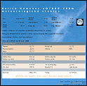
At first, some basic information about the modul DRA818V.
 | ") |  |
| DRA818V dimensions | Pins description | |
 |  | |
| limit values | some of the parameters | RF parameters |
The FM TRX consists of two printed circuit boards. These are interconnected by shielded cables with PSH-PFH connectors.
The smaller PCB contains:
- Stabilizer of the supply voltage
- SDR module Dorji DRA818V (U)
- Low pass filter of harmonic frequencies at RF output
- Audio Frequency Amplifier LM386N-4 for speaker connection
- Transistor for switching output RF power (1W/100mW)
 |  |  |  |
| Schematic in higher resolution | Check of gerber files in online viewer | PCB manufactured in Seeedstudio.com | Assembled PCB |
The power supply voltage from the power connector marked +12V- goes through the protective diode D2 and is connected to both the 5V stabilizer and the output connector (marked AUX) from which the second PCB is powered. I used the type for current of 2 Ampers. The producer of DRA818V writes that the current consumption at a higher output power is 750mA. I have measured that the whole TRX takes at full power slightly over 900 mA. The stabilizer burns relatively high power and it necessarily needs a cooler. The input power supply voltage could be lower, let's say around 7.5V, so that the loss at the stabilizer would not be so high. A further diode that follows the stabilizer reduces the supply voltage to around 4.3V. According to the datasheet the DRA818V works in the range 3.3V - 4.5V. Apparently it is designed to power from one LiPol cell.
There are three blocking smd ceramic capacitors 100n, 10n, 1n close to the DRA818V feed pin.A higher harmonics filter (Low Pass Filter) is connected to the DRA818V antenna input/output. It is necessary there. Without the LPF the unwanted radiation does not meet the regulations. The filter coils are 5.5mm in diameter (I wound them using the cylindrical part of a drill). L1 and L2 have 4 threads and L3 has 3 threads of copper enameled wire of 0.5-1mm diameter. In the first prototype I fine-tuned the filters with capacitive trimmers. But they are quite expensive and today they are poorly available. That's why I used only fix capacitors C3=C6=33pF and C4=C5=56pF in this version and I tuned the filter by stretching the coil's threads. These capacitors must be of good quality. I used ceramic from NP0. The latest version of PCB is designed for smt capacitors in LPF because today they are much more easily available.
I tuned the filter using the antenna analyzer MiniVNA. (A new version MiniVNA-Tiny supposedly works up to 3 GHz and in range up to 70 dB, but so far I haven't had a chance to try it). Then I tested the harmonics suppression and output power using the SA44-Signalhound USB Spectrum Analyzer. SA44-Signalhound.
 |  |  |  |
| Draft of the LPF in AADE filter design 4.5 | Real design of LPF Notice the smd capacitors | Tuning using MiniVNA | Check of output SWR |
 |  |  |
| Output RF power +30.3dBm | Check harmonics suppression | Setting modulation of 1750Hz |
The DRA818V audio output connects through the R1 to the volume potentiometer. The potentiometer is located on the second PCB (the front subpanel with MCU and display) and is connected by a shielded cable via a 3-pole PSH connector (volume). The potentiometer value should be somewhere in the range of 5kΩ to 50kΩ and should be logarithmic for smooth volume control. Resistance of R1 should be somewhere in the range of kΩ and its value sets a reasonable volume control range depending on the potentiometer value and the AF output level of the DRA818V. (Moreover, the AF signal level at the DRA818V output can be programmed in eight levels, as described in this article below).
The Audio Frequency Power Amplifier is a common LM386N used according to the datasheet. Capacitor C16 is not necessary to install, C7-100nF is more than enough.
Transistor T1 switches the PWR_H/L pin of the DRA818V to ground. According to the datasheet, the output power is lower by 3dB (half power), when the pin is switched to the GND. Any small universal NPN transistor can be used here. I designed the PCB for 2N3904.
The second PCB is also used as a front subpanel and it contains:
- Stabilizer of the supply voltage
- MCU Atmel (now Microchip) AVR Atmega 328(P) (also ATmega88, ATmega168)
- LCD alphanumeric display 2x16 characters
- Six buttons
- Volume potentiometer
- Microphone connector
- Microphone amplifier
 | ||
| Schematic in higher resolution | Check of gerber files top side | Check of gerber files bottom side |
 | ||
| Partially assembled top side | Partially assembled bottom side | Partially assembled |
The method of stabilizing the supply voltage is similar to that of the other board. If the supply voltage is supplied from the AUX output of the other board, it is not necessary to use the input protective diode (replace it with a piece of wire). This board takes max about 100mA (it depends mainly on the LED backlight of the display that does NOT go through the stabilizer). That's why the 1A stabilizer is more than enough and it doesn't need any radiator.
As the main control center of the entire transceiver serves the Atmel (Microchip) AVR MCU Atmega328(P). In the first version I have used Atmega48. Essentially, any of the Atmega8, 48, 168, 328 series could be used here. The pin layout and functions are almost identical for this use, only the memory size varies. It would only be necessary to compile a program for a particular type of MCU. Atmega328 are now widely used in the popular Arduino and therefore their price is often lower than those with less memory. Occasionally, Atmega328P with a bootloader for Arduino can be bought very cheap. We can just delete the bootloader using the programmer and we can use the MCU for our design.
An alpha numeric display of 2x16 characters is connected to the MCU. Displays can be purchased in many different designs. This particular version, on which the PCB is designed, has an outer dimensions of 80x36mm, the pitch between the screw holes is 75x31mm and the pins are in the upper left row when viewed from the front (see photograph). The display is backlit by LEDs. The contrast trimmer R2, 10kΩ adjusts the contrast of the display (angle of view). The transistor T1 (BC337-40) switches the cathode of the backlight LEDs against the ground. Again, it is possible to use any universal NPN transistor (TUN), we only have to be careful of the layout of the pins. The current of the LEDs is given by R1 (consider its power load with respect to the supply voltage). The resistor R12, parallel to the T1 transistor, is not necessary. However, if we use a display where nothing is visible without illumination (usually blue backlit display with white characters), we light up a little the LED backlight with this resistor, so it can be read even when the LED is "OFF".
The transceiver is controlled by the six buttons and the PTT switch on the microphone. Switronic microswitches, of a total length of 17 mm are used as buttons to reach through the front panel.
 of VHF FM TRX with DRA818V") | ") | ") |
| Wiring of the MIC socket | FM TRX - front view | FM TRX - view from above |
The eight-pin straight RJ45 socket is used to connect the microphone. It is wired in the manner to match the microphone for the Yaesu FT817. The 3 microphone buttons are wired in parallel to the microswitches on the subpanel, so they function similarly to the FT817:
Dwn-tune down, Up-tune up, hold the Fst increases the tuning stepIn the previous version, I had a problem with modulation because the dynamic microphone does not give the modulation signal strong enough. So I added a microphone amplifier with one transistor T2. Again, we can use essentially any small universal NPN transistor. Of those I had in a drawer the BC546-B was the least noisy. When you use something like 2N3904, be careful about pin layout. The drawing on the PCB wil probably not match the shape of the housing.
The component values in the amplifier schema correspond to the use of a FT817 microphone with a dynamic insert. If you use different microphone (eg an electret), it will be necessary to adjust the gain of the preamplifier by changing the resistance R7 in the transistor emitter (increasing the value decreases the gain and vice versa). Also, it would be good to change the C7 value (cut of higher frequencies) according to the output impedance of the microphone. In the case of using the electret, use the pin 3 of the microphone connector, which is the output of about 4.3V.
Compared to the previous version, I added the ability to transmit a "repeater power up tone" of 1750Hz. This is still in use on some VHF repaters, for example OK0C. The frequency 1750Hz is generated by the MCU on a pin 24, port_C.1. Trimmer R9, 100Ω sets the correct level of modulation. The tone is triggered by holding the PTT button on the microphone while briefly pressing the BT6 (Alt) button. Generating the tone lasts about 2 seconds. For this purpose, I have added the transistor T3 (BC337-40) and the components around it, thanks to which the MCU recognizes the active PTT.
A volume potentiometer is also placed on the subpanel, and is connected to the other PCB via a shielded cable and the three-pin PSH-PFH connector.
Another shielded cable with connector connects the microphone amplifier output with the DRA818V modulation input as well as the PTT switch.Most of the communication between the subpanel board and the DRA818V board is in series using the HW UART, which is part of both the MCU and the DRA818V. The physical connection is again via shielded cable and PSH connector. Communication is only one-way, Atmega328(P) sends the data, DRA818V receives. The MCU software does not check whether the commands were accepted. For example, if we set the frequency outside the DRA818V range, this will appear on the display, but DRA818V will not accept it.
The switching of the output RF power is through the logical level on the pin 18, Port_B.4 of the MCU. It uses a connector that is destined for MCU programming (pin 2 on the programming connector). The signal leads by wire to the other, smaller PCB, whereby the R4, 2k2 resistor switches the transistor T1 and thus switches the output power. According to the manufacturer's datasheet, the power reduction should be by 3 dB, ie by half. According to my measurement, the power is lower by 8 dB and the piece differs from the piece.
I wrote the program in my favorite editor/compiler BASCOM_AVR, version 2.0.7.7. The compiled code occupies about 16% of the Atmega328(P) memory. It would probably not fit into Atmega48, which has only 4kB of program memory (But I did not try). The BASCOM_AVR editor has a feature that makes it easy to create a well-formatted .html file from the source code. (The source code text can be copied from the browser screen, pasted into the BASCOM_AVR editor, and customized to fit your own ideas.)
The source code (I tried to comment it enough) and both the compiled .hex and .bin, for ATmega328P are packaged together with some other files in a .zip file that is stored in the Download section of this site.
 | ||
| Setting of FUSE-bits | ||
The program uses an internal RC oscillator of the MCU. Therefore, it is necessary to set the "fuses" so that the 8MHz internal RC oscillator is used and turn off the frequency division of eight (as default the division is on). It is also good to set "brown_out" to 2.7V (there will be a reset when the voltage drops below this value).
Control description:
After the program is loaded into the memory of a MCU, the frequency is set to 145.500 MHz, the transmitter CTCSS is turned on (but none tone is set) and high power (1W) is set. Note: As long as the programmer is connected, we should not switch the power because the pin that controls power is also one of the programming inputs. All the buttons BT1 to BT5 have two different functions, depending on whether the BT6 button (labeled ALT) is being held.
Functions of buttons in basic mode:
- BT1 - steps the frequency up by 12.5 kHz
- BT2 - steps the frequency down by 12.5 kHz
- BT3 - steps subtone (CTCSS) up
- BT4 - steps subtone (CTCSS) down
- BT5 - switches an "repeater operation". There are 3 states: Normal, Reapeater and Listening at the input frequency.
Functions of buttons while holding the BT6 (Alt)
- BT1 - steps the frequency up by 25 kHz
- BT2 - steps the frequency down by 25 kHz
- BT3 - CTCSS On/Off (3 states: no CTCSS, Tx only, both Tx and Rx)
- BT4 - turns the backlight On/Off
- BT5 - power switching (1W/Low)
- PTT - transmit of a modulation tone of 1750Hz for about 2 seconds. During this time, the backlight of the display is lit. (It also works in reverse - first press and hold PTT and then briefly BT6)
Whenever any button (except BT6) is pressed, the backlight of the display lights up. Then, if we do not press anything for about 8 seconds, the backlight of the display goes out and at that moment all of the currently displayed values (except for the power setting) are stored in the EEPROM memory. From there, they are loaded the next time the FM radio is turned on. If a stored frequency value is not normally used for FM modulation or outside the amateur band (here it is below 144.500 MHz and above 145.800 MHz), the 145.500 Mhz frequency is set when resetting (power off and on). When setting the frequency (BT1 and BT2 buttons), between the values of RX 145.600 MHz and 145.800 MHz the repeater operation is automatically switched on (-600 kHz for TX). But using the BT5 button you can set a different state. CTCSS tone frequencies are displayed without decimal places (just not enough space on display).
PWR ON setting
Volume and Squelch
- If we hold the BT1 button immediately after turning on the power, we will jump to the basic volume level and the noise-gate level (Squelch).
- BT3 - Increasing volume (maximum 8)
- BT4 - decrasing volume (minimum 1)
- BT5 - increasing quelch value (maximum 8)
- BT6 - decreasing quelch value (minimum value 0 = continual noise)
- BT2 - return to normal TRX operation
If we do not press anything for about 8 seconds, the backlight of the display goes out and at that moment both the values are stored in the EEPROM memory. During TRX volume and squelch setup, the TRX normally works on the channel it was previously turned Off (if the values were stored in EEprom), so adjustments can be made when listening to the traffic.
 |  |
| Setting of power-on volume and squelch | Setting of power-on audio filters |
Audio filters setting
- If we hold the BT3 button right after turning on the power, we get into the audio filters setting.
- BT2 - switching Pre/De-emphasis On/Off
- BT4 - switching the High-Pass Filter On/Off
- BT6 - switching the Low-Pass Filter On/Off
- BT5 - return to normal operation
If we do not press anything for about 8 seconds, the backlight of the display goes out and at that moment the values are stored in the EEPROM memory. Note:
Even if he DRA818V accept the audio filters commands, I have never noticed any change in the received signal. My impression is that this feature simply does not work. On the other hand these features work wel with DRA818U (the UHF version). If I have missed something or I have not understood how this setting should work, I will be glad if someone explains it to me. Thanks a lot.Now i found out that it works.
Download for UHF version.
The source code (I tried to comment it enough) and both the compiled .hex and .bin, for ATmega328P are packaged together with some other files in a .zip file that is stored in the Download section of this site.
Few words about the LPF filter of UHF (70cm) version:
All three low-pass coils have 2 threads. I made them using a copper wire 0.65 mm wound on a cylidrical part of a 5mm diameter drill. Certainly, it would be better to use a thicker and even a silver-covered wire. The L1 and L3 are stretched at the spacing of the solder pads on the printed board, the L2 has the threads pressed together with a gap of about 1 mm. The design can be seen in the photos. I used capacity trimmers 2.5-22 pF (VISHAY BFC2_808 ...). But it seems to me that for these frequencies they are not very suitable. Perhaps it would be better to use solid capacitors values and fine tune the filter by stretching the coil threads. So the new version of the PCB has pads for SMT capacitors. You can calculate exact values of components for the filter using program AADE Filter Design. I would like to point out that tuning of the LPF for the 70cm version is much more difficult than the version for 2m.Since the PSH connector at the RF output is not the best, I replaced it by SMA in the new version.
 |  |
| suggestion of UHF LPF component values | New version of RF/AF board |
Jarda, ok1hdu
FM QRP transceiver with DRA818V or DRA818U and Oled display (08.01.2020)
FM transceiver s DRA818V nebo DRA818U a OLED displejem (29.12.2019)
Poslední verze transceiveru 2m FM s modulem DRA818V (16.09.2016)
UKV (70cm) FM transceiver s modulem DRA818U (29.05.2015)
VKV FM modul DRA818V uvnitř. (12.05.2015)
První pokusy s UKV FM transceiverem s modulkem Dorji DRA818U (30.04.2015)
Finální (prozatím) verze VKV (2m) FM TRXU s DRA818V (11.04.2015)
FM TRX 145MHz s modulkem Dorji DRA818V (29.03.2015)
Postavte si svého Baofňuka (Wouxunga, Luitonga, Quanshenga, ...) (13.02.2015)
| Novinky |
|
07.07.2023: Update na webu DXFC Dneska jsem updatoval info na webu DXFC.
05.07.2019: Update fotoalba Do fotoalba jsem přidal pár fotografií ze:
Slovinska (červen 2019) Fotoalbum prozatím zrušeno. 05.12.2018: Update fotoalba Do fotoalba jsem přidal pár fotografií ze:
Slovinska (jaro 2018) a ze: Suchého Vrchu (zima 2005/2006). Fotogalerie je prozatím zrušena. |
| kalendář |
| |||||||||||||||||||||||||||||||||||||||||||||||||
| Radary ČHMU |
|
| Zaparkováno na: |

|
| TSL certifikát: |

|


Tento web site byl vytvořen prostřednictvím phpRS - redakčního systému napsaného v PHP jazyce.
Na této stránce použité názvy programových produktů, firem apod. mohou být ochrannými známkami
nebo registrovanými ochrannými známkami příslušných vlastníků.